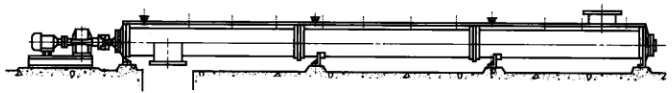
Layout form of horizontally installed screw conveyor
The spiral machine body includes head bearings, tail bearings, suspension bearings, spiral, housing, cover plate, and base.
Due to the reasonable installation time of the drive device and discharge port at the head section (with thrust bearings), it can make the screw
The pipe shaft is in a stretched state. In addition, each spiral section (head section, middle section, tail section) is arranged in the order of spiral arrangement.
Arrange the length of the sections in order and arrange the spiral sections of the same specification together, which will bring convenience to design, manufacturing, and ordering.
It should be arranged at the joint of the hood and above the suspension bearing.
③ There are six common structural arrangements for screw conveyors,
The installation forms of screw conveyors mainly include: ground support installation, suspension support installation, installation in corridors or trenches, and installation of two units working in series. The following requirements should be met during installation and adjustment: 1. The material trough and the spiral shaft should maintain good coaxiality. 2. The connection between each section of the material trough should be tight and there should be no misalignment. Gaskets can be added between sections and between the top cover and the trough to increase the sealing of the trough. At the same time, the length error of the trough can also be adjusted. 3. The gap between the inner wall of the hopper and the surrounding area of the spiral body should be equal. 4. The drive device shaft and the screw shaft should maintain good coaxiality. When adjusting, the height of the driving device can be adjusted with the help of shims. 5. After the installation of the spiral body, it should undergo a static balance test. 6. The intermediate suspension bearing should properly support the connecting shaft to prevent radial deformation of the helical shaft. Installation can be achieved by adjusting the shims between the bearing shells to meet the requirements. After the installation of the whole machine is completed, check whether there are any debris inside the machine and whether sufficient lubricating oil is added to each lubrication point. During the no-load test, the bearings must not leak oil and the temperature rise of the bearings should not exceed 20 ℃. During load testing, the temperature rise of the bearing shall not exceed 30 ℃.